m. Сміла, Незалежності, 67г. оф, 406/6













Deye SUN-110K-G03 (110 kW) - three-phase grid-tie inverter


Description Deye SUN-110K-G03
A hundred and ten kilowatts: the largest grid-tie inverter in the catalogue
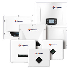
The SUN-110K-G03 feeds 110 kW into a three-phase grid with a 121 kW peak and accepts an array of up to 150 kW across six MPPT trackers with four strings each. This is the upper limit of the G series in this catalogue: anything larger is built as a set of several such machines on a common switchboard. A housing of 838 × 568 × 326 mm at 81 kg and an output current reaching 183 A place the unit among equipment connected to the site's own transformer substation. Typical users are large warehouses with cold rooms, grain elevators, greenhouse complexes, plants with heavy daytime load, or ground-mounted stations covering several hectares. The inverter is grid-tie: it has no battery and stops when voltage disappears, so process continuity is secured by other means.
A hundred and eighty-three amps per phase: the limit of a single cable run
Rated output current is 166.7 A per phase at 380 V and 159.4 A at 400 V, with a maximum of 183.3 A. Such current calls for a 250 A breaker and 120 mm² copper or 185 mm² aluminium cable, which is the practical limit of a single run — beyond it, two parallel runs are used. Laying, fixing and terminating cable of that size is done to a design, with thermal calculations for the tray and torque control at every terminal. The distance to the connection point becomes a key cost parameter: sometimes it is cheaper to place the inverter nearer the substation and run a longer DC line than to pull 120 mm² across the whole site. Generation of 110 kW can only be registered to a legal entity, and the permitted capacity in the connection agreement must cover that level in full.
A 458-volt threshold: why those ten extra kilowatts need longer rows
Six trackers of 40 A give 240 A of DC, exactly as in the SUN-100K-G03 (item 2076), but the rating here is 10 kW higher. Hence the higher voltage demand: delivering 110 kW requires the array to hold about 458 V instead of the 417 V needed by the hundred. In modules that is a difference of roughly one or two extra panels in every row, and on a constrained roof it can prove insurmountable. The calculation must be done for a hot day, when voltage sags 10–15 % below nameplate: if the summer figure comes out at 430 V, the rated 110 kW will only appear in cool sunny weather. Where long rows are impossible, the hundred with its lower threshold will deliver more real kilowatt-hours than a hundred and ten that never reaches its rating.
The same 150 kW array and a ratio of 1.36
Maximum module power for this model is the same as for the hundred — 150 kW — so the oversizing ratio is 1.36 rather than 1.5. In practice that means less peak clipping: in summer the inverter hits its ceiling less often and the daily curve comes out smoother and more predictable. For a site that exports to the grid this is an advantage, because every clipped peak hour is revenue not earned. For a zero-export site the logic reverses: there the hundred with its larger array wins, because what matters is not the nameplate rating but the area under the curve during working hours. The choice between these two models is therefore decided by how your plant operates, not by the figure on the case.
Twenty-four strings across a large field
Six trackers of four strings give twenty-four independent groups, and on a ground-mounted station that allows the field to be divided into six sections with their own geometry. For an array of identical high-current modules the optimum is still three strings per tracker: four at 13–14 A each exceed 50 A and breach the 40 A operating limit. Eighteen strings of thirteen to fourteen panels comes to around two hundred and fifty modules, which is a full field or two to three industrial roofs. Lay the array out so that strings sharing one tracker have identical orientation, otherwise the tracker settles on a compromise point and gives away percentages. The spare capacity of a sixth tracker also helps future expansion: new rows are connected without reworking the part already installed.
Four thousand metres of altitude and the thermal regime at 110 kW
The maximum operating altitude without derating is 4000 m, twice the two thousand of the SUN-60K-G (item 2066) and SUN-80K-G (item 2069). At sea level that margin turns into thermal comfort: a cooling circuit designed for thin air runs underloaded in ordinary conditions. This matters precisely at a hundred and ten kilowatts, where peak heat output exceeds a kilowatt and any worsening of heat removal immediately eats into power. The operating range runs from minus twenty-five to plus sixty-five degrees, but above forty-five the unit reduces output smoothly, so room ventilation or outdoor shading affects generation directly. Noise of up to 55 dB together with that heat output means a dedicated plant room or an outdoor mount under a canopy with restricted access.
98.8 % efficiency and the losses of a 150-kilowatt plant
Peak efficiency of 98.8 % and a European weighted figure of 98.3 % are the highest in the series, and at this power level they translate into concrete numbers. A 150 kW array in central Ukraine produces around 155 MWh a year, so conversion losses come to roughly 2.6 MWh — less than the annual consumption of a single apartment. MPPT efficiency above 99 % across six trackers minimises mismatch losses: each section of the field holds its own optimum independently of the others. Harmonic distortion below 3 % at over a hundred kilowatts of output is mandatory for operation through your own substation, otherwise both the transformer and reactive power compensation suffer. An integrated DC isolator, ground fault monitoring and type II surge protection on both sides complete the set required for industrial service.
How it differs from its neighbours in this catalogue
The SUN-100K-G03 (item 2076) is the same housing, the same 81 kg and the same 150 kW array, but rated at 100 kW with a lower 417 V threshold, so for a roof with short rows it is objectively the better unit. The SUN-80K-G (item 2069) in a 60 kg housing is simpler to install, yet has only four trackers and needs 500 V for full power. The SUN-60K-G (item 2066) and SUN-50K-G03 (item 2072) remain the choices for connections up to sixty kilowatts. If you need more than a hundred and ten kilowatts, several machines are installed in parallel on a common board — standard practice, and it also gives redundancy should one of them fail. For autonomy no G-series model will do: backup is built on three-phase LP3, SM2 or HP3 hybrids, or on a diesel generator with automatic transfer.
Send us a site plan, the lengths of the rows you can actually fit and the capacity permitted by your agreement, and we will check whether your array reaches 458 volts and whether the hundred is the better buy than the hundred and ten.
Characteristics Deye SUN-110K-G03
Reviews about Deye SUN-110K-G03 from real users
No reviews found